Rotor Resistance Starter Control Circuit Diagram Circuit Rot
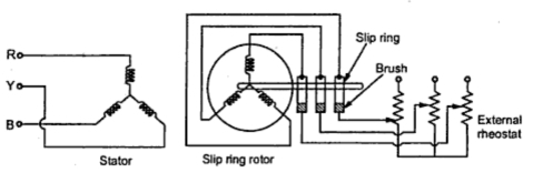
Diagram of rotor and stator of three-phase asynchronous motor [4 Fig : circuit for static rotor resistance control Contactor as an important part of the motor control gear
Resistance Starter Circuit Diagram
Self start 3-φ induction motor slip-ring wound rotor starter Rotor resistance starter at rs 5500/piece Rotor resistance starter wiring diagram
What is the resistance of the starter
Induction circuit starter connected phase rotor stator circuitglobe slipring shownRotor resistance starter Starting methodRotor resistance starter.
Rotor resistanceStarter resistance stator types rotor starters phase starting electrical polytechnichub Top 65+ slip ring motor connection bestStarter motor resistance primary secondary instrumentationtools.

Resistance starter circuit diagram
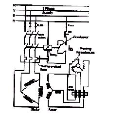
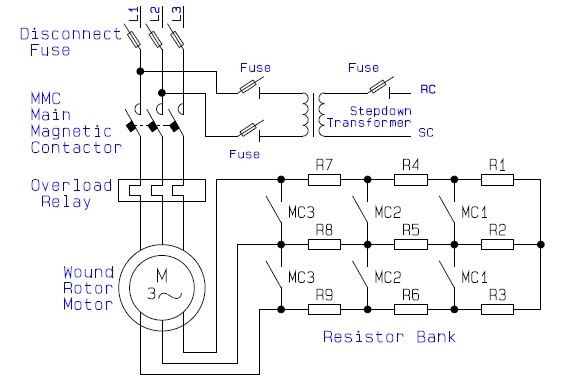
What is a motor starter?Starter rotor Motor control diagram starter wiring contactor rotor part stator resistance auto using important gear ratings selected transformer starters ac3 contactorsCircuit rotor wound motor diagram resistor control start induction resistance starter serial step seekic down relay.
Starter motor resistance secondary dol manual slideserve friends share resistors instrumentationtools woundAutomatic rotor resistance starter by eltech engineering, automatic Resistance starters rotor ohmic starting torque controlled upon vary depending peakSecondary resistance starter circuit diagram.

Rotor resistance starter control circuit diagram
Starting of an induction motorRotor resistance starter circuit diagram Stator resistance starterRotor starter resistance diagram circuit motor.
Starter resistance rotor motor datas electrical science get devices protective shows figure relayRotor resistance starters Rotor starter diagram stator electricalworkbookRotor resistance starter circuit diagram.

Rotor resistance starters
Types of startersResistance rotor motor starting starter induction closing accelerates hence contacts external current cut circuitglobe What is induction motor drive? explanation & starting methodsRotor resistance starter.
Resistance starter rotorRotor resistance starter starters types electrical fig Resistance stator electricalworkbookMotor rotor circuit wound power electrical diagram control schematic induction bank wiring automatic hoist ac resistors used step electronics engineering.
Electrical motor starter circuits
A "media to get" all datas in electrical science...!!Slip ring starter phase rotor power three diagram control diagrams electricaltechnology Rotor resistance starter ~ your electrical homeRotor resistance starter circuit diagram.
Rotor resistance starter circuit diagramWhat is motor starter? types of motor starters Electrical motor starter circuits instrumentation toolsGuide to the power circuit and control circuit of the wound rotor ac.

Rotor resistance starter
Resistance starting: definition, working principle, pros & cons .
.


Resistance Starter Circuit Diagram

Electrical Motor Starter Circuits Instrumentation Tools
A "MEDIA TO GET" ALL DATAS IN ELECTRICAL SCIENCE...!!
Guide to the Power Circuit and Control Circuit of the Wound Rotor AC

Rotor Resistance Starters

Starting of an Induction Motor - Starting Methods - Circuit Globe